Why the RJ45 plug connection diagram matters for home security cameras
For a home security camera, the humble RJ45 plug connection diagram often decides whether images are crisp or frustratingly unstable. When the connector and its wiring are assembled correctly, the network remains stable and the camera streams video without random drops or pixelated frames. A single misplaced wire in the cables can instead cause intermittent ethernet failures that are very hard to diagnose.
Most modern IP cameras rely on ethernet cables rather than Wi-Fi when homeowners want dependable data transmission. The RJ45 plug connection diagram shows how each of the eight wires must sit in the connectors to respect the wiring standard used by your lan. By following this wiring guide carefully, you ensure that the camera, the recorder, and the computer all share the same language for ethernet connections.
In practice, the diagram is a visual map of wire pairs, colors, and pin numbers that keeps networks consistent. The green and orange pairs, along with the remaining wires, must follow either T568A or T568B wiring diagram layouts. When every network cable in the house respects the same base standard, crossover cables and straight cables behave predictably with all devices.
Homeowners often underestimate how much poor cable crimping can affect security footage quality. A badly terminated ethernet cable may still let some internet things traffic through, but it can fail under the constant upload load of multiple cameras. Understanding the RJ45 plug connection diagram therefore becomes a practical skill, not just a technical curiosity, for anyone serious about home surveillance.
Understanding colors, wire pairs, and wiring standards for IP cameras
The RJ45 plug connection diagram always starts with color codes, because colors prevent confusion during crimping. Each ethernet cable contains four twisted wire pairs, and these pairs are usually green, orange, blue, and brown in different striped and solid versions. The wiring standard defines which color goes to which pin, ensuring that cables connect cameras and routers in a predictable way.
For most home networks, T568B is the most common wiring guide, especially when mixing older and newer devices. In this wiring diagram, the orange pair carries the primary data transmission, while the green pair often handles the secondary channel in ethernet connections. When every connector in the house follows T568B, straight cables and crossover cable types can be identified and used correctly.
Some installers still prefer T568A, particularly when integrating things IoT sensors and low power devices alongside cameras. The RJ45 plug connection diagram for T568A simply swaps the green and orange wire pairs, but the remaining wires stay in the same order. Problems arise only when one end of a network cable uses T568A and the other end uses T568B unintentionally.
For Power over Ethernet cameras, correct wiring is even more critical because both power and data share the same cables. A miswired connector can interrupt power delivery, leaving a camera offline even though the lan switch seems fine. To deepen your understanding of how cabling interacts with advanced detection features, you can read about how sensor shock technology elevates modern home security cameras and then relate those features back to stable ethernet cables.
Straight cables, crossover cables, and where they fit in home security
When reading any RJ45 plug connection diagram, you will encounter both straight cables and crossover cables. Straight cables use the same wiring standard at both ends, so the connector pinout is identical from camera to router. These ethernet cables are ideal for linking home security cameras to switches, NVRs, and the main lan infrastructure.
Crossover cables intentionally swap the transmit and receive wire pairs between ends. In practice, this means the green and orange wires change positions according to the wiring diagram, allowing two similar devices to communicate directly without a switch. Older networks sometimes needed crossover cables to connect a computer directly to another computer or to certain legacy devices.
Modern switches and cameras often support auto MDI-X, which can adapt to either straight cables or crossover cable types automatically. However, relying on this feature without understanding the RJ45 plug connection diagram can still cause confusion when troubleshooting ethernet connections. For critical home security installations, many professionals still label cables clearly and keep crossover cables separate from standard network cable runs.
When a camera stops recording or drops off the network, the cable is often suspected first. A cable tester can quickly verify whether the wires follow the correct wiring standard and whether any wire pairs are broken. If the tester shows a mismatch, redoing the cable crimping with a proper crimping tool and following the diagram usually restores stable data transmission and reliable footage, especially when combined with checks on why a security camera is not recording on the SD card.
Step by step: from raw cable to reliable RJ45 connector
Turning a raw ethernet cable into a dependable RJ45 connector starts with preparation. First, cut the network cable cleanly, then strip about 2 cm of the outer jacket without nicking the wires inside. You will see four twisted wire pairs that must be untwisted only as much as necessary to follow the RJ45 plug connection diagram.
Arrange the wires into the correct order for your chosen wiring standard, usually T568B in home networks. This means placing the orange and green wires in their precise sequence, followed by the blue and brown pairs, before trimming them evenly. Keeping the untwisted length short helps maintain signal integrity and reduces interference in ethernet connections.
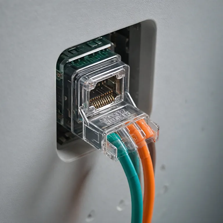
Next, insert the wires carefully into the RJ45 connector, ensuring each wire reaches the front and sits in the correct channel. The transparent plastic makes it easier to compare your work with the wiring diagram, checking that the colors match the expected pattern. Once satisfied, use a quality crimping tool to perform the cable crimping, applying firm pressure until the connector’s metal contacts pierce the insulation of each wire.
After crimping, always test the cable with a cable tester before connecting it to cameras or other devices. The tester will confirm that all eight wires are correctly mapped and that no crossover cables were created accidentally when you needed straight cables. For homeowners who prefer visual aids, many manufacturers provide a pdf wiring guide that illustrates every step, from arranging the wires to verifying the final connector for robust data transmission to home security cameras.
Testing, troubleshooting, and maintaining camera network cables
Even when you follow the RJ45 plug connection diagram perfectly, real homes introduce dust, movement, and wear that can affect cables. A network cable running through a door frame or under a carpet can experience repeated stress that slowly loosens the connector. Over time, this can cause intermittent ethernet failures that only appear when the camera is streaming high resolution footage.
Regular testing with a cable tester helps catch these issues before they compromise security. By checking continuity and pin order, you confirm that the wiring diagram is still respected and that no wire pairs have broken inside the sheath. If a test fails, cutting back the damaged section and redoing the cable crimping with a new connector is often faster than trying to salvage the old plug.
When troubleshooting, always inspect both ends of the ethernet cable, including the ports on the camera and the switch. Dust or oxidation on the metal contacts can interfere with data transmission, especially in humid environments or near outdoor entrances. Cleaning the ports gently and reseating the connectors can restore stable ethernet connections without replacing the entire cables.
For more complex networks that mix cameras, computers, and other internet things devices, documenting each RJ45 plug connection diagram used in the installation is wise. Labeling cables with their destination and whether they are straight cables or crossover cables simplifies future upgrades and repairs. If you want broader context on planning a resilient surveillance setup, consult in depth home security blogs that actually help you choose the right cameras, such as this expert guide to selecting home security cameras, and then align your cabling strategy with the recommended camera types.
Planning future proof cabling: from copper to fiber optic for home surveillance
As home security systems grow, the RJ45 plug connection diagram remains central, but planning must also consider future technologies. Many homeowners start with a few ethernet cables for basic cameras, then later add more devices, NVRs, and even things IoT sensors. Without a structured approach to wiring, the lan can become a tangle of cables that are hard to maintain or upgrade.
When designing a new installation, think about where cameras, computers, and other devices will likely be placed over the next several years. Run extra network cable lines to key locations, terminating them in wall plates with clearly labeled connectors that follow a single wiring standard. This approach reduces the need for ad hoc crossover cables and keeps ethernet connections consistent throughout the property.
For longer runs or high bandwidth needs, especially when multiple high resolution cameras share the same path, consider integrating fiber optic segments. While fiber optic cables use different connectors than RJ45, they can link distant parts of the home network back to a central switch, where standard ethernet cables then connect to cameras. The RJ45 plug connection diagram still governs these final copper links, ensuring that wire pairs and colors align with the rest of the networks.
Many professional installers provide a pdf map of the entire cabling layout, including each connector, cable route, and wiring diagram used. Keeping such documentation alongside your cable tester and crimping tool makes future troubleshooting far easier. By treating cabling as a long term investment rather than a quick fix, you support reliable data transmission for every present and future home security camera on your property.
Key statistics about RJ45 cabling and home security camera reliability
- Up to 80 % of IP camera connectivity issues in homes are traced back to incorrect connector pinouts or damaged ethernet cables.
- Structured cabling with a single wiring standard can reduce troubleshooting time for home networks by more than half.
- Using a cable tester after every crimping operation can cut long term cable failure rates by a significant margin.
- Properly installed Cat 5e or Cat 6 network cable can typically support PoE cameras over distances of about 90 to 100 m in residential environments.
Common questions about RJ45 plug connection diagrams for home security cameras
How does an RJ45 plug connection diagram affect camera image quality ?
The RJ45 plug connection diagram determines whether data transmission between the camera and the recorder is stable. If the wiring standard is not respected or wire pairs are mixed, packets can be lost, leading to dropped frames or pixelated images. Correct wiring ensures that the ethernet cable supports the full bandwidth required for high resolution video.
Do I need crossover cables for modern home security cameras ?
Most modern cameras and switches support auto MDI-X, which can adapt to either straight cables or crossover cables. For typical home installations, straight cables wired according to a single standard are sufficient for all ethernet connections. Crossover cables are mainly useful when directly connecting similar devices without a switch, which is rare in current home surveillance setups.
Can I mix different categories of ethernet cables in the same camera network ?
You can mix Cat 5e, Cat 6, and higher categories as long as each connector follows the correct RJ45 plug connection diagram. However, the overall performance will be limited by the lowest category of network cable in the path. For consistent results, many homeowners choose one category for all new cables connect to cameras and recorders.
Is fiber optic necessary for a residential camera system ?
Fiber optic is not strictly necessary for most homes, but it becomes useful when distances are long or when many high resolution cameras share the same backbone. In such cases, fiber optic links can carry aggregated traffic back to a central switch, where standard ethernet cables and RJ45 connectors serve individual devices. The decision depends on property size, camera count, and future expansion plans.
Should I terminate my own RJ45 connectors or buy pre made cables ?
Pre made ethernet cables are convenient and reduce the risk of wiring errors, especially for beginners. However, learning to follow an RJ45 plug connection diagram and using a crimping tool gives you flexibility to create custom lengths and tidy installations. Many homeowners adopt a mixed approach, using pre made cables indoors and custom terminated network cables for longer or concealed runs.